|
|
|
Usuarios conectados
Actualmente hay 5833 visitantes online. |
|
Productos
|
|
Información
|
|
Destacado
|
|
|
 |
|
|
No hay comentarios de productos.
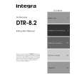
DTR-8.2 PANEL VIEWS
REAR PANEL 3
(RI) The terminal on the DTR-8.2 is for connecting other Integra/ Onkyo components equipped with the same terminal. When a component is -connected, you can point the remote controller supplied with the DTR-8.2 at the sensor on the DTR-8.2 and operate that component without having to switch remote controllers. In addition, by connecting components to the terminal, you can also perform the system operations given below. Power on/ready function When the DTR-8.2 is in the standby state, if an -connected component is turned on, then the DTR-8.2 also turns on and the input source selected at the DTR-8.2 automatically switches to that component. If the power cord for an -connected component is connected to the AC OUTLET on the DTR-8.2, or if the DTR-8.2 is turned on, this function will not work. Direct change function When the play button is pressed at an -connected component, the input source selected at the DTR-8.2 automatically changes to that component. Power off function When the DTR-8.2 is placed in the standby state, all -connected components are also automatically put into the standby state. CAUTION If an MD recorder is connected to the TAPE jack on the DTR-8.2, switch the Input Selector from TAPE to MD.
IR IN/OUT If the DTR-8.2 is located inside a rack or cabinet that will not allow infrared beams to reach the IR sensor, you will need to connect a remote sensor to IR IN input to be able to use the remote controller. Then install the remote sensor in an unblocked location where you can easily point the remote controller. Using a mini-jack connector, connect the IR emitter to the IR OUT terminal on the DTR-8.2 and then place the IR emitter on the remote sensor of the component or facing it.
RS 232 The RS 232 port is to be used in conjunction with an external controller to control the operation of the DTR-8.2 by using an external device. The RS 232 port may also be used in the future to update the operating software of the DTR-8.2 so that it will be able to support new digital audio formats and the like as they are introduced.
VIDEO IN/OUT These are the video inputs and outputs. On the rear panel, there are five video inputs and two video outputs and each one includes both composite video and S video configurations. Connect VCRs, LD players, DVD players, and other video components to the video inputs. The two video output channels can be used to be connected to video tape recorders for making recordings. � When connecting a VCR or other video component, make sure you connect the audio and video leads together (i.e., both to VIDEO 3).
MULTI CHANNEL INPUT By connecting a DVD player, MPEG decoder, or other component that has a multi channel port, you can playback the audio with 5.1 channel or 7.1 channel output. So, be sure to prepare a cable that can properly connect the DTR-8.2 to the peripheral device. connector
Front output L (white)
DTR-8.2
REMOTE CONTROL
Ex: Integra/Onkyo CD player connector Ex: Integra/Onkyo cassette tape deck
R (red) Subwoofer
DIGITAL OUTPUT
OPT
1
R
FRONT
PRE OUT
L
SUB 2
CENTER
L (white) Surround
COAX 1
SURR SURR BACK / ZONE 2
2
R (red)
3 OPT 1
C
FRONT
MULTI INPUT
CENTER
To connect components using the terminal, simply connect a remote control cable from this terminal to the terminal of the other component. An remote control cable with a 1/8-inch (3.5mm) miniature two-conductor plug comes with every cassette tape deck, compact disc player, MD recorder, and DVD player that has an terminal. � When performing operations with -connected components using the system, do not use the remote zone (Zone 2). � For remote control operation, the audio connection cables must also be connected. � If a component has two terminals, you can use either one to connect to the DTR-8.2. The other one can be used to daisy chain with another component.
Ex: DVD-Audio player/MPEG decoder
R (red) Surround back L (white) Center
SUB
2 3
SURR SURR BACK
R
4
L
GND DIGITAL INPUT
GND Use this GND terminal for connecting the ground (or earth) wire if a turntable is connected.
|
|
|
> |
|